Motivations
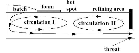
Two different types of glass melting furnaces are commonly used in the glass industry: (1) Float glass furnaces: are often open cross-fired regeneration furnaces consisting of melting and conditioning regions connected by a waist. The bottom of the tank is often stepped. This type of furnaces is fairly large and used to produce large quantity of glass products such as flat glass sheets. (2) submerged throat furnaces are used, for example, to produce glassware, container glass, and TV panels and funnels (see Figure 1). They consist of a melting tank and a working section connected by a channel or throat.
The introduction of the batch into the furnace can be either from the back wall in the longitudinal direction or from the sides by using different types of chargers. The resulting batch coverage can assume many different shapes from a uniform blanket to dispersed batch logs floating at the surface of the glass melt. Many design parameters and operating conditions should also be considered in the combustion space for example: (i) the fuel (natural gas, fossil fuel or coal), (ii) the oxidizer (air or commercial grade oxygen), (iii) the shape of the flame, and (iv) the regeneration. Thanks to the development of numerical methods in particular, finite-difference methods and the increases in both computing speed and capacity, computer simulations of glass melting furnaces have been the object of intensive research over the last two decades. Computer simulations provide valuable alternatives and supplemental tools to (a) direct observations and measurements in actual furnaces and (b) physical models, for improved design and control of glass melting furnaces. Recent publications indicate that the glass flow could become chaotic under certain operating conditions. if this were true, the furnace would be impossible to control and numerical simulations pointless. This project aims at improving the understanding of physical phenomena affecting the gravity driven flow structure in the glass melt. The effect of several critical parameters are assessed in order to simulate glass melting furnaces in a more realistic manner. The results are of significant importance in improving the furnace performances in term of glass quality and energy efficiency.
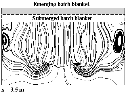
Figure 1: Formation of Rayleigh-Benard cells under the batch blanket at 3.5 m from the wall.
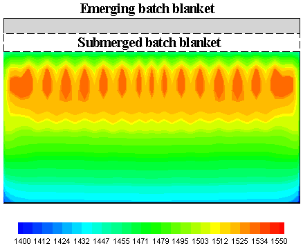
Figure 2: Sample calculations of the temperature at the midplane when the batch blanket is submerged.
Figure 3: Sample calculations of the velocity fields at the midplane when the batch blanket is submerged.
Figure 4: Sample calculations of the streamline at the midplane when the batch blanket is submerged. Publications
L. Pilon, 2002. Interfacial and Transport Phenomena in Closed-Cell Foams. UMI#3105002, UMI, Ann Arbor, MI, 2002. L. Pilon, G. Zhao, and R. Viskanta, 2002. Three-Dimensional Flow and Thermal Structure in Glass Melting Furnaces. Part II: Effect of Batch and Bubbles. Glass Science and Technology, Vol. 75, No.3 pp. 115-124. 4. L. Pilon, G. Zhao, and R. Viskanta, 2002. Three-Dimensional Flow and Thermal Structure in Glass Melting Furnaces. Part I: Effect of the Net Heat Flux Distribution. Glass Science and Technology, Vol. 75, No.2 pp. 55-68. |


