Abstract
This study examines the benefits of adding microencapsulated phase change material (PCM) to concrete used in building envelopes to reduce energy consumption and costs. First, it establishes that the time-dependent thermal behavior of microencapsulated PCM-concrete composite walls can be accurately predicted by an equivalent homogeneous wall with appropriate effective thermal properties. The results demonstrated that adding microencapsulated PCM to concrete resulted in a reduction and a time-shift in the maximum heat flux through the composite wall subjected to diurnal sinusoidal outdoor temperature and solar radiation heat flux. The effects of the PCM volume fraction, latent heat of fusion, phase change temperature and temperature window, and outdoor temperature were evaluated. Several design rules were established including (i) increasing the PCM volume fraction and/or enthalpy of phase change increased the energy flux reduction and the time delay, (ii) the energy flux reduction were maximized when the PCM phase change temperature was close to the indoor temperature, (iii) the optimum phase change temperature to maximize the time delay increased with increasing average outdoor temperature, (iv) in extremely hot or cold climates, the thermal load could be delayed even though energy flux reduction was small, and (v) the choice of phase change temperature window had little effect on the energy flux reduction and the time delay. This analysis can serve as a framework to design PCM composite walls in various climates and seasons and to take advantage of time of use electricity pricing.
Effective heat capacity method for simulating phase change
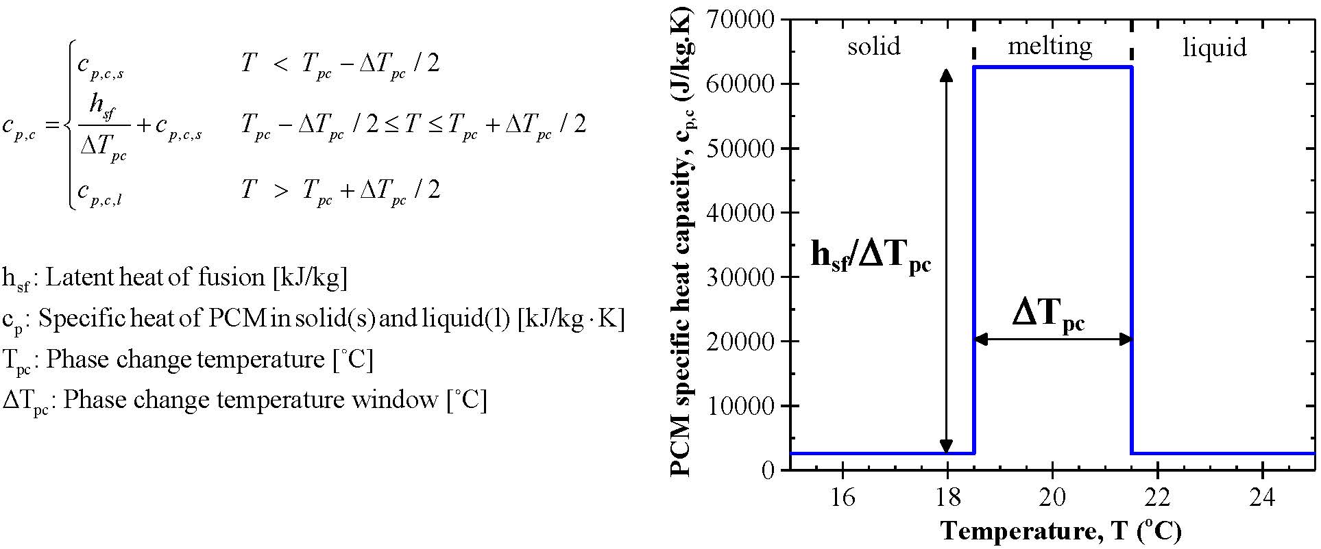
To account for the latent heat stored during phase transition, the PCM specific heat can be defined as a piecewise function of temperature given by the effective heat capacity method and shown in Figure 1. This is an idealized representation of the PCM specific heat. In reality, PCMs exhibit superheating and subcooling during melting and freezing, respectively, delaying phase change and causing hysteresis in the cp,c(T) plot.
Schematics and Assumptions
Figure 2 illustrates a heterogeneous slab of a three-component composite material consisting of aligned unit cells of monodisperse microcapsules filled with PCM and embedded in a concrete matrix in an FCC packing arrangement and an equivalent homogeneous slab with some effective thermal properties. It also shows the associated coordinate system and the boundary conditions used to validate the effective homogeneous model. The overall thickness of this composite slab was denoted by L.
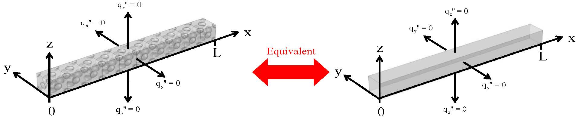
Figure 2. Schematic of a heterogeneous slab consisting of aligned unit cells of microencapsulated PCM distributed in concrete with a face-centered cubic (FCC) packing arrangement and an equivalent homogeneous slab with some effective thermal conductivity keff and effective volumetric heat capacity (ρcp)eff..
To make the problem mathematically tractable, the following assumptions were made: (1) All materials were isotropic and had constant properties except for the temperature-dependent PCM specific heat. (2) The PCM specific heat was the same for solid and liquid phases. (3) Interfacial contact resistances between the concrete, the shell, and the PCM were negligible. (4) Natural convection in the molten microencapsulated PCM was absent based on the fact that the Rayleigh number was very small. (5) There was no heat generation in the wall.
Governing equations and boundary conditions
The temperature T in the homogeneous material equivalent to the heterogeneous wall of identical dimensions was governed by
![]()
where αeff(T) = keff / (ρcp)eff(T) and is the effective thermal diffusivity. Note that αeff(T) is a function of the local temperature T since it accounts for the temperature-dependent specific heat of the PCM. However, a consistent model for the effective volumetric heat capacity (ρcp)eff and the effective thermal conductivity keff of the composite wall needs to be specified. To approximate the heterogeneous composite by a homogeneous medium with some effective thermal properties, its effective volumetric heat capacity can be expressed as,
![]()
where ϕc and ϕs are the volume fractions of the core and shell materials, while (ρcp)c, (ρcp)s, and (ρcp)m are the volumetric heat capacities of the core, shell, and matrix materials, respectively. By defining cp,c(T) based on the effective heat capacity method, (ρcp)eff(T) can be expressed as,
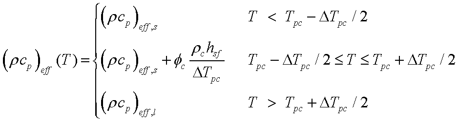
where (ρcp)eff,s is the effective volumetric heat capacity of the PCM-concrete composite wall with unmelted PCM given by
![]()
Here, it was assumed to be equal to the effective volumetric heat capacity of the composite with fully melted PCM, i.e., (ρcp)eff,s = (ρcp)eff,l. Moreover, Felske [1] used the self-consistent field approximation to derive an effective medium approximation (EMA) to predict the effective thermal conductivity keff of monodisperse spherical capsules randomly distributed in a continuous matrix given by,
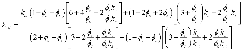
This expression was validated using detailed numerical simulations of ordered and randomly distributed monodisperse and polydisperse microcapsules. Convective heat transfer was imposed at the interior wall surface x = L with a constant indoor temperature Tin maintained by the HVAC system so that,
![]()
where hi is the indoor mixed convective heat transfer coefficient accounting for both forced and natural convections. Combined convective and radiative heat transfer was imposed at the exterior wall surface given by,
![]()
where ho is the outdoor convective heat transfer coefficient, Tsky represents the average sky temperature, αs and ε are the total hemispherical absorptivity and emissivity of the outdoor wall surface, respectively, and σ is the Stefan-Boltzmann constant, i.e., σ = 5.67x10⁻⁸ W/m2K4. The ambient outdoor temperature was imposed as a sinusoidal function of time t (in s) expressed as,
![]()
where Tmax and Tmin are the maximum and minimum outdoor temperatures during a day, respectively. A phase shift of 2π/3 placed the peak outdoor temperature Tmax at 2:00 pm, as the daily maximum occurred between 1:00 pm and 3:00 pm for more than 80% of the year in California climate zone 9 (Los Angeles, CA) based on weather data. Similarly, the solar radiation heat flux q"s(t) as a function of time t (in s) was imposed as,
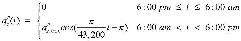
where q"s,max(t) is the maximum daily solar radiation heat flux (in W/m2). Here, the maximum daily solar radiation heat flux q"s,max(t) was taken as 535 W/m2 and occurred at 12:00 pm corresponding to the average daily maximum value and time throughout the year in California climate zone 9.
Results and Discussion
Figure 3 shows the area-averaged inner surface heat flux as a function of time for PCM volume fraction ϕc of 0.5, 0.25, and 0.4. It also shows the corresponding predictions of the heat flux for the equivalent homogeneous slab with the above mentioned effective thermal properties. In all cases, the average relative difference in the predicted area-averaged inner surface heat flux between the heterogeneous composite slab and the equivalent homogeneous slab was less than 2% at all times when the inner surface heat flux was greater than 5% of its steady-state value. Figure 3 also demonstrates that increasing the PCM volume fraction decreased the inner surface heat flux at all times and delayed its steady state. This can be attributed to the fact that adding PCM not only enhanced the latent and sensible thermal mass of the composite material but also its thermal resistance.
|
Figure 3. Area-averaged inner surface heat flux predicted for the heterogeneous three-phase 1 mm thick slab and the corresponding homogeneous slab with effective thermal properties as a function of time t for T(0,y,z,t) = T0 = 20°C and T(L,y,z,t) = TL = 37°C. Values of effective volumetric specific heat and effective thermal conductivity were (ρcp)eff,s = 2.04, 2.08, and 2.11 MJ/m3 and keff = 1.23, 0.94, and 0.75 W/m.K corresponding to PCM volume fractions of ϕc = 0.05, 0.25, and 0.4, respectively. The phase change properties were taken to be hsf = 180 kJ/kg, Tpc = 20°C, and ΔTpc = 3°C.
|
|
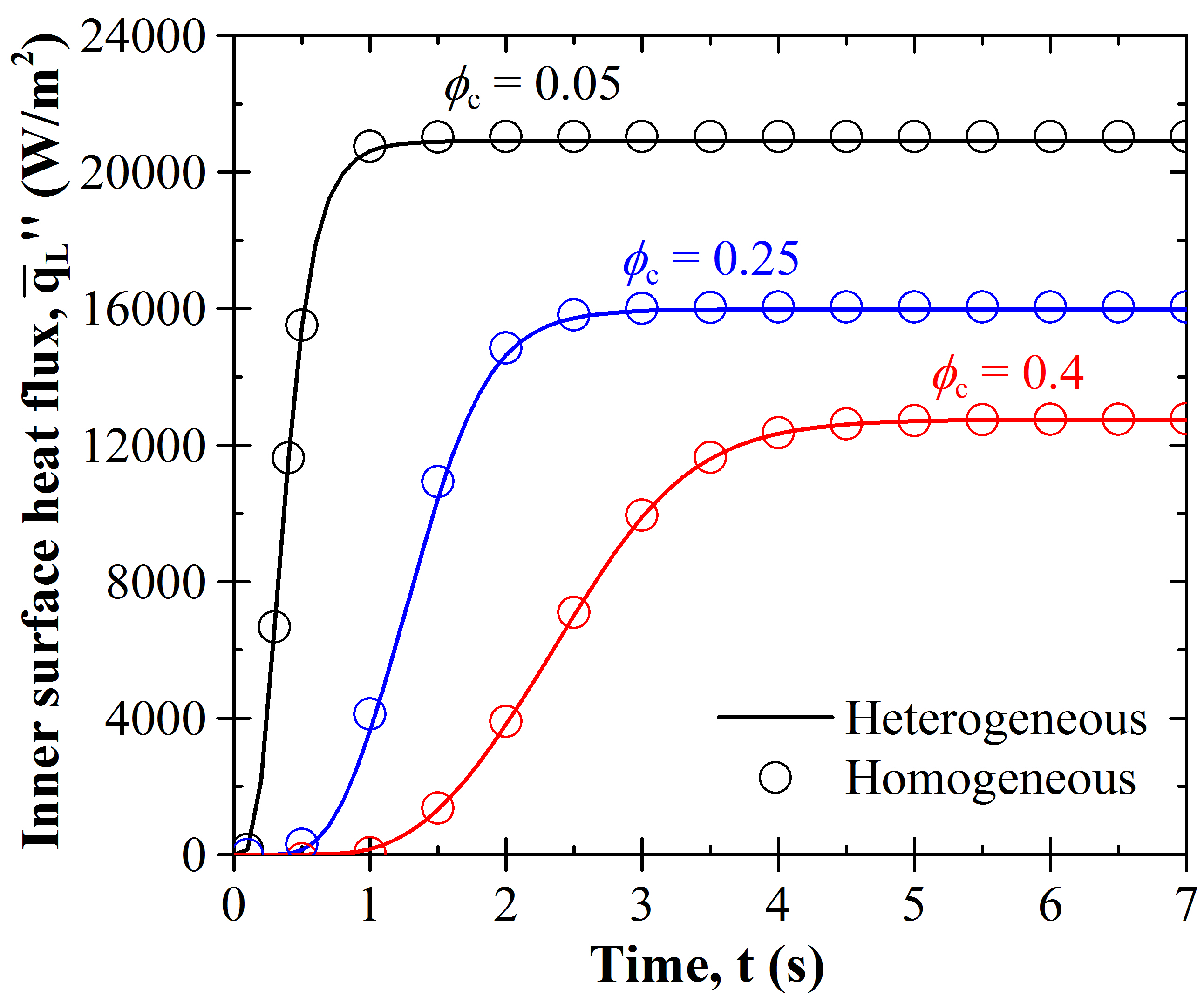
Figure 4a plots the inner wall heat flux as a function of time for PCM volume fraction ϕc ranging from 0.0 to 0.5. It demonstrates that increasing the PCM volume fraction significantly reduced the heat transfer through the wall. In fact, a PCM volume fraction ϕc of 0.5 reduced the range of variation in the inner wall heat flux by more than 90% compared with plain concrete. Figure 4b plots the energy flux reduction Er as a function of PCM volume fraction ϕc ranging from 0.0 to 0.5. In the absence of phase change, Er increased linearly with increasing ϕc due to the associated increase in thermal resistance and sensible heat storage of the wall, i.e., keff < km and (ρcp)eff,s > (ρcp)m. The energy flux reduction Er was notably larger when phase change was accounted for. Figure 4c shows the time delay τd in the maximum inner wall heat flux as a function of PCM volume fraction ϕc. It indicates that τd increased significantly with increasing PCM volume fraction, reaching more than 13 hours for ϕc of 0.5. Here also, the contribution of phase change to the time delay was important and dominated over that of other thermal effects.
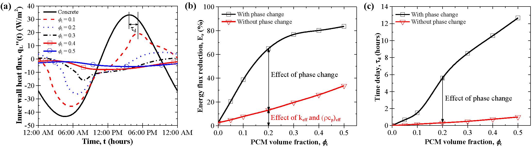
Figure 4. (a) Inner wall heat flux q"L(t) as a function of time through a 10 cm thick microencapsulated PCM-concrete wall subjected to sinusoidal diurnal boundary conditions with Tmin=10°C and Tmax= 30°C. (b) Energy flux reduction Er and (c) time delay τd for PCM volume fraction ϕc ranging from 0.0 to 0.5. Here, hsf = 180 kJ/kg, Tpc = 20°C, and ΔT pc=3°C. The PCM specific heat was either constant and equal to (ρcp)eff,s or temperature-dependent to assess the effects of phase change.
Figure 5a plots the energy flux reduction Er as a function of phase change temperature Tpc for average outdoor temperature (Tmax + Tmin)/2 of 10, 20, and 30°C and for ϕc=0.1, hsf = 180 kJ/kg, and ΔTpc = 3°C. For an average outdoor temperature of 20°C, a distinct maximum energy flux reduction Er,max of 39% was achieved for a phase change temperature Tpc equal to the indoor temperature Tin of 20°C. Overall, there were no optimization opportunities in terms of energy reduction for a homogeneous PCM composite wall subjected to sinusoidal outdoor temperature oscillations and solar radiation heat flux in extremely hot or cold climates. Figure 5b plots the time delay τd as a function of phase change temperature Tpc for ϕc=0.1, hsf = 180 kJ/kg, and ΔTpc = 3°C. In all cases, τd reached a maximum ranging from 2 to 3 hours as the average outdoor temperature decreased from 30 to 10°C. Indeed, adding PCM to a building wall in an extremely hot or cold climate may still provide financial savings to the ratepayer if TOU pricing is available, by shifting the heating or cooling load to an off-peak time of day.
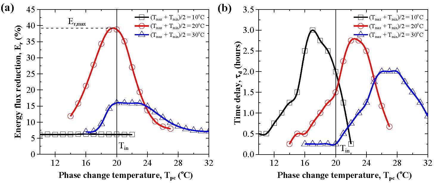
Figure 5. (a) Energy flux reduction Er and (b) time delay τd as a function of phase change temperature Tpc for average outdoor temperature (Tmax + Tmin)/2 of 10, 20, and 30°C and outdoor temperature amplitude (Tmax - Tmin)/2 of 10°C. Here, ϕc = 0.1, hsf = 180 kJ/kg, and ΔTpc = 3°C.
Figure 6a plots the maximum energy flux reduction Er,max as a function of the average outdoor temperature (Tmax + Tmin)/2 ranging from 5 to 35°C for outdoor temperature amplitude (Tmax - Tmin)/2 of 10 or 15°C. It reveals that the maximum energy reduction could reach up to 40% and was achieved when the average outdoor temperature was about 22°C for both outdoor temperature amplitudes of 10 and 15°C. These results confirm that phase change had no effect on the daily energy flux reduction in extreme hot or cold climates. Figure 6b plots the optimum phase change temperature corresponding to the maximum energy flux reduction Tpc,opt,Er as a function of average daily outdoor temperature ranging from 5°C to 35°C and for outdoor temperature amplitude of 10°C and 15°C. It shows that Er,max was achieved for an optimum phase change temperature Tpc,opt,Er near the indoor temperature Tin± 1°C, regardless of the average daily outdoor temperature.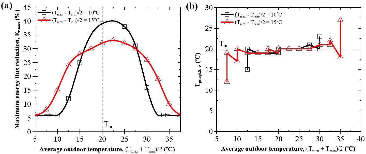
Figure 6: (a) Maximum energy flux reduction Er,max and (b) phase change temperature corresponding to the maximum energy flux reduction Tpc,opt,Er for average outdoor temperatures ranging from 5 to 37.5°C with an amplitude of either 10 or 15°C. Here, ϕc = 0.1, hsf = 180 kJ/kg, and ΔTpc = 3°C.
Conclusion
This study demonstrated that a composite wall containing microencapsulated PCMs can be accurately represented as a homogeneous wall with effective volumetric heat capacity (ρcp)eff thermal conductivity keff. This time-dependent homogeneous thermal model was used to establish important design rules that can inform the selection of microencapsulated PCMs for concrete walls in various climates. First, adding microencapsulated PCM to concrete walls and increasing the latent heat of fusion both substantially reduced and delayed the thermal load on the building. Second, the phase change temperature leading to the maximum energy flux reduction was equal to the desired indoor temperature regardless of the climate conditions. Third, to achieve the maximum time delay, the optimum phase change temperature increased with increasing average outdoor temperature. Fourth, in extremely hot or cold climates, the use of PCM delayed the thermal load to take advantage of TOU pricing even though the energy flux reduction were not significant. Lastly, the phase change temperature window had little effect on the energy flux reduction and the time delay. This analysis can inform future simulations of composite walls containing microencapsulated PCMs in any climate.
References
- J.D. Felske, 2004. Effective thermal conductivity of composite spheres in a continuous medium with contact resistance. International Journal of Heat and Mass Transfer, Vol. 47, pp. 3453-3461. doi:10.1016/j.ijheatmasstransfer.2004.01.013
- A.M. Thiele, A. Kumar, G. Sant, and L. Pilon, 2014. Effective Thermal Conductivity of Three-Phase Composites Containing Spherical Capsules. International Journal of Heat and Mass Transfer, Vol. 73, pp. 177-185. doi: 10.1016/j.ijheatmasstransfer.2014.02.002
- A.M. Thiele, G. Sant, and L. Pilon, 2014. Diurnal Thermal Analysis of Microencapsulated PCM-Concrete Composite Walls. Energy Conversion and Management, Vol. 93, pp.215-227. doi:10.1016/j.enconman.2014.12.078